

Suitable handling precautions must be observed during device measurement and system design. The following guidelines are essential to achieve high performance of a device with similarly high reliability.
1. Absolute Maximum Ratings
Be careful never to exceed, even momentarily, the absolute maximum ratings specified in the data sheets herein. Pay particular attention to the following points.
- It is possible for diodes to be damaged by spike current, generated when switching the power ON or OFF or when adjusting its output voltage. Before activating diodes, check the transient state of the power supply to assure that it does not exceed the maximum voltage rating.
- Operate the diodes below the maximum optical output power rating in order to prevent mirror facet damage and resultant loss in reliability.
- Maximum Ratings are defined at 25°C case
- DO NOT apply higher reverse voltage than Maximum Rating
2. Surge Energy
Electrostatic discharge and electric spike input which may damage the diodes should be prevented. The main causes of undesirable surge energy are static electricity on the human body, shipping containers made of unsuitable materials, abnormal pulses generated from test equipment, and voltage leakage from soldering irons.
Precautions below should be taken when using diodes.
- The human body should be grounded through a high resistance about 1 MW while handling diodes in order to prevent diode destruction due to static electricity contained in the body and clothes.
- Soldering irons should be grounded to prevent voltage leakage from transferring to the diodes.
- Suitable materials should be chosen for shipping containers and jigs so that they will not become charged with static electricity by rubbing during Use of electro-conductive materials or aluminium foil is effective.
3. Storage
- Keep the recommended storage conditions at a temperature of 5 to 40°C and a humidity of 20 to 70%, and keep it as low as possible and low humidity as possible. It is recommended to use diodes within 2 years of shipment. Avoid sharp drops in temperature in order to prevent It is recommended to store diodes in an atmosphere of dry nitrogen with a dew point of -40°C.
- Assure that the storage atmosphere is void of dust and gases harmful to diodes.
- Use a storage case which cannot easily be charged with static electricity.
4. Safety Considerations
Laser beam may cause injury to the eyes, skin, etc., regardless of invisible appearance. Please pay attention to the following during usage:
- Do not look directly into the emitting part of the laser beam or the focused beam especially when operating the laser diode.
- When observing the laser beam path, please use a fluorescent plate or an infrared camera.
- When using a laser diode for medical equipment, special attention is required, so please consult us in advance.
- For laser safety, please follow JIS C 6802 “Radiation safety standard of laser products”, 21 CFR Part 10.
- Also, please be sure to confirm the details with the latest version of JIS C 6802, 21 CFR Part 1040.10 and take necessary safety measures.
5. LD-package Handling
- Take care not to touch the window glass directly. Contamination and scratches on the window surface will result in decreased optical power output and distorted far field Contamination can usually be wiped off using a cotton swab with ethanol.
- Do not squeeze the cap tightly, as it will cause the window glass to crack and package hermeticity to deteriorate.
- Do not bend the bottom of the lead wire, as it will cause the glass area to crack and the hermeticity to deteriorate.
- Do not cut, process, or deform the package as much as possible. When it is absolutely necessary to perform press fitting etc. for heat radiation , please pay close attention so that it will not affect the LD, PD, wire, glass cap etc. by excessive external force.
Mounting a diode on a thermal radiator
Laser diodes must be mounted on thermal radiators. For higher reliability, it is necessary to minimize mechanical stress to the packages and achieve sufficient heat sinking. Attention should be paid to the following items when mounting diodes on thermal radiators.
- Use a copper or aluminium plate for the thermal The plate should be larger than 50 X 50 X 2 mm3.
- To provide good thermal conductivity, polish the thermal radiator surface so it will lie flat with the diode heat. Finish the radiator surface to keep bumps, twists, or bends below 0.05 mm.
- Do not solder packages to thermal radiators, as this may result in excessive temperature to the assemblies inside the packages or loss of package hermicity.
- When mounting the diodes, do not touch or hit them against the caps, to prevent the window glass from becoming contaminated or cracked.
- Do not use silicone grease, as it may contaminate the window glass.
Soldering
- Soldering point must be away by 1.0mm or more from the bottom of lead wires.
- Do not allow the scattered flux to adhere to a glass window or a lens.
- Soldering time should be 260°C or less, within 10 seconds, or 350°C or less, within 3.5 seconds.
6. Advice for Beginners
Avoiding surge energy
Laser diodes are easily destroyed by static electricity. To prevent electrostatic discharge, pay attention to the following precautions as well as table 1 when handling diodes and designing application circuits.
- Set the electric potential of the work bench to the same as that of the power supply ground line.
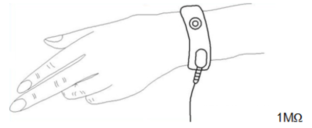
- Ground the operator’s body by wearing a wrist band as shown in figure 1, and connect it to the same potential as the power supply ground line.
- Do not operate equipment which may generate high frequency surge energy near diodes. The lead wires of drive circuits pick up surge electricity which may destroy diodes in the induced electric field.
Ways to Prevent Surge Destruction of LDs (Examples)
Item | Check Points | Specification Examples |
Human body | Ground operator’s body. | Place a non-metallic, carbon band with a resistance of 1M Ohms on their wrist. |
Commonly ground the measuring and inspecting equipment and the work bench. | Should be carried out in shielded rooms as well. | |
Control the ground level. | Under 10 Ohms | |
Power supply | Distribute power from main power supply through noise filter to each measuring and testing unit. | |
Insert noise filter in each power supply unit. | Organize with capacitors and resistors. | |
Keep the main power supply in the on-state, and switch the power on and off using an external switch. | ||
Set up sequence control for turning the power supply off during electric outages. | ||
Eliminate relay chattering. | ||
To prevent chattering, avoid turning the APC circuit or relay switch on and off as much as possible. | ||
Working conditions | Temporarily stop work when the power supply for lights or other equipment connected to the same power line is turned on or off. | |
Conduct diode packing and measuring while performing ion blowing or in a weak minus ion atmosphere. | ||
Select the right soldering iron. | Battery operated soldering iron. | |
Jigs and other considerations | Make carrier jigs and packing cases conductive. | Particularly the cases. |
Place conductive mats on the working floor. | 1×10⁶ Ohms~1×10⁹ Ohms | |
Control room temperature and humidity. | Humidity should be 50 ± 10%. | |
Make short circuits between diode leads. | ||
Do not use sticky volume knobs. | Periodically replace with new ones. |
Operating LD
When operating the LD, please note the following points.
- Please install heat Its size depends on the time and output to operate, but please use a comparatively large heat sink (50 X 50 X 2 mm3 copper or aluminium) if the initial condition cannot be determined.
- If possible, supply air from fan. Even with a comparatively small air volume, the heat dissipation effect can be obtained and the risk of LD being destroyed can be reduced.
- It is preferable that the drive circuit has an APC (Automatic Power Control) function. However, as the circuit becomes complicated, there are many cases where the drive circuit is destroyed by an adjustment mistake, so it is only necessary to first operate the actuator. For this purpose, we recommend a simple constant current circuit.
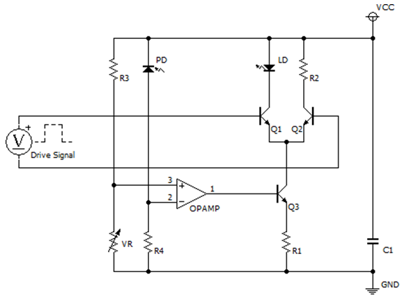
- An example of the LD drive circuit is shown in Figure In Figure 2, a constant current circuit that determines the current that the LD lights up is configured with an operational amplifier, a transistor Q3, and a resistor R1. When implementing APC, please control the base potential of transistor Q3.
- In addition, as a circuit that modulates LD, high speed switch circuit composed of transistor Q1 and transistor Q2 is When LD is modulated at high speed, LD can be modulated at high speed by inputting a small amplitude differential signal to the base potential of transistors Q1 and Q2.
- Please decide an appropriate value for power supply voltage VCC according to the drop voltage of LD. For example, in the case of infrared LD or red LD, it is generally considered that about 5 V to 6 V is considered in consideration of the voltage drop of the LD and the operating voltage of the transistor.
- By configuring such a circuit configuration, it is possible to keep the current flowing from the power supply VCC constant, so it is possible to realize an LD drive circuit with stable circuit operation with little variation in power supply current.